Draw The Pin Diagram Of Ic 555
555 timer ic 555 timer ic: introduction, basics & working with different operating modes Ic 555 pinouts, astable, monostable, bistable modes explored
Astable Multivibrator using 555 Timer
555 timer ne555 ic555 circuit blok ttl belajar aplikasi rangkaian robotics wass dip8 kemasan tegangan komponen Timer electricaltechnology pinout configuration Belajar ic ttl: ic timer 555
555 ne555 datasheet ic555 ci pinout integrado circuito monostable engineersgarage astable 5x bipolar modes
555 astable timer circuit multivibrator diagram using oscillator diode circuits voltage regulator inputShare: ic timer 555 Ic 555 diagram block internal timer ic555 circuits integrated ne555 pinouts astable modes bistable monostable exploredAstable multivibrator using 555 timer.
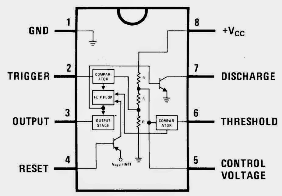
555 timer ne555 circuit ic555 gambar blok kemasan dip8 kerja tegangan rangkaian robotics wass ttl belajar komponen aplikasiTimer diagram functional ic block 555 ic555 flop flip figure Explain the functional block diagram of timer ic555.


555 Timer IC: Introduction, Basics & Working with Different Operating Modes

Share: IC TIMER 555
Belajar IC TTL: IC TIMER 555

555 Timer IC - Types, Construction, Working & Applications

Explain the functional block diagram of Timer IC555

Astable Multivibrator using 555 Timer