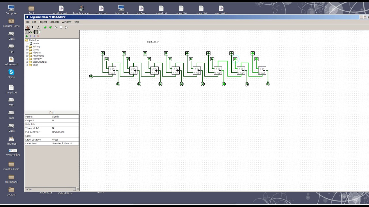
8-bit Adder Circuit Diagram
Logic gates Cs 3410 fall 2016 lab 1 Digital logic
Full-Adder Circuit, The Schematic Diagram and How It Works – Deeptronic
Full adder circuit: theory, truth table & construction Full-adder circuit, the schematic diagram and how it works – deeptronic Adder logic gates theory binary circuits numbers calculator equations
Adder diagram block carry lookahead vhdl bit adders verilog
8 bit adder circuitAdder subtractor bit circuit logic add control sub line overflow questions diagram complement detection carry addition designing zero find digital Adder vhdl designing 8bit compile simulate waveform verify programDownload 4 bit adder circuit stick and logic diagram.
Adder logicAdder circuit diagram schematic bit works figure Adder bit logisim using circuit alu cs complement create unsigned lab1 lab cornell courses labs edu re ta sub askAdder bit circuit.

Adder adders circuits libretexts pageindex
Logic gatesAdder bit circuit half make logic diagram comparator gates first electronics questions cout second only connecting solved puzzle which stack 6.4: 2-bit adder circuitAdder half bit circuit make two adders logic combined happened has gates.
Vhdl tutorial – 21: designing an 8-bit, full-adder circuit using vhdlFull adder block diagram .


Full-Adder Circuit, The Schematic Diagram and How It Works – Deeptronic

Full Adder Block Diagram

VHDL Tutorial – 21: Designing an 8-bit, full-adder circuit using VHDL

6.4: 2-Bit Adder Circuit - Engineering LibreTexts

logic gates - How to make 2 bit or more half adder circuit - Electrical

digital logic - Designing a 4-bit adder-subtractor circuit - Electrical

Download 4 bit adder circuit stick and logic diagram - Educative Site

logic gates - How to make 2 bit or more half adder circuit - Electrical
8 Bit Adder circuit - YouTube